Problem
I was alerted to a Samsung PS60E8000 plasma TV which had gone off with a large bang tripping the circuit breaker in the house.
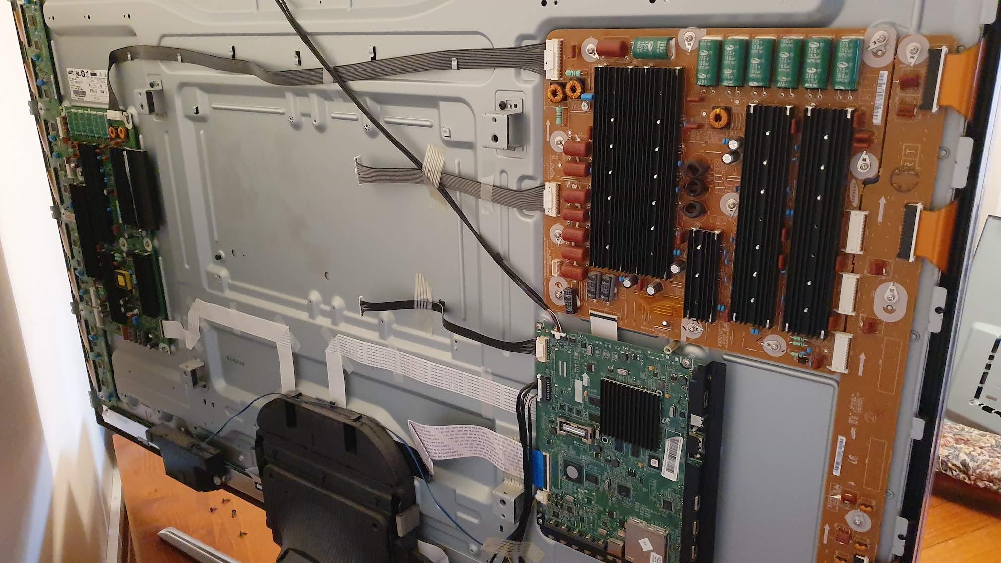
Realising the TV is now almost 7 years old any repair would be on the cusp of uneconomical. However not wanting to send the TV to landfill, I opened it up.
Diagnosis
The symptom of a loud bang, plus the absense of any red standby LED meant the likely culprint was the power supply unit (PSU). The PSU was marked BN44-00514A. Querying Samsung and other retailers new boards are no longer manufactured and remanufactured boards were in the realm of $150-200AUD. However the TV set would be a write off anyway I decided to delve deeper.
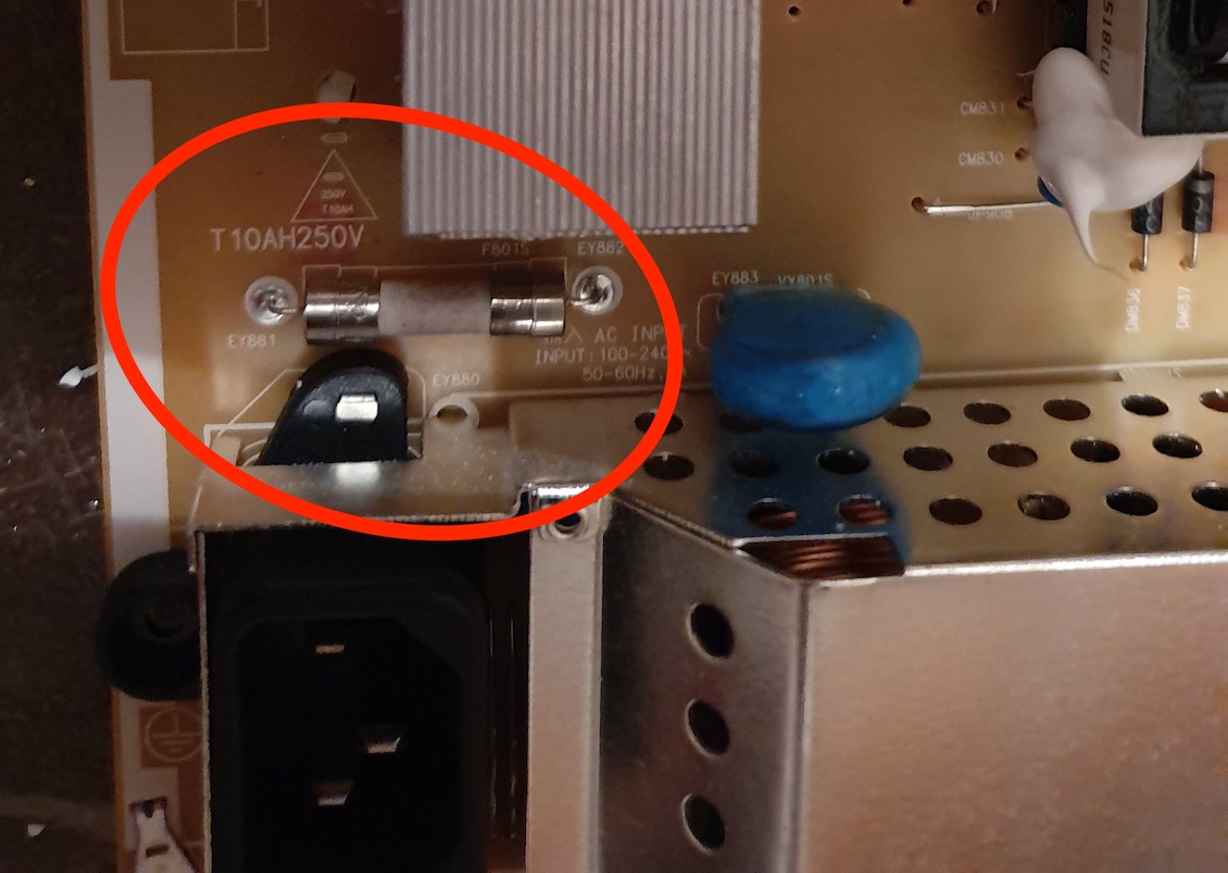
All the capacitors on the board looked ok, and there was no obvious burning. The main input fuse (10A 250V Slow Blow) had opened.
Tracing downstream of fuse there is a bridge rectifier (15A 400V TS15P05G) [Datasheet]. Measuring across this I found the + terminal shorted to one of the AC terminals. A bridge rectifier should not have any direct shorts between any terminals, as there is a minimum of 1 diode between.
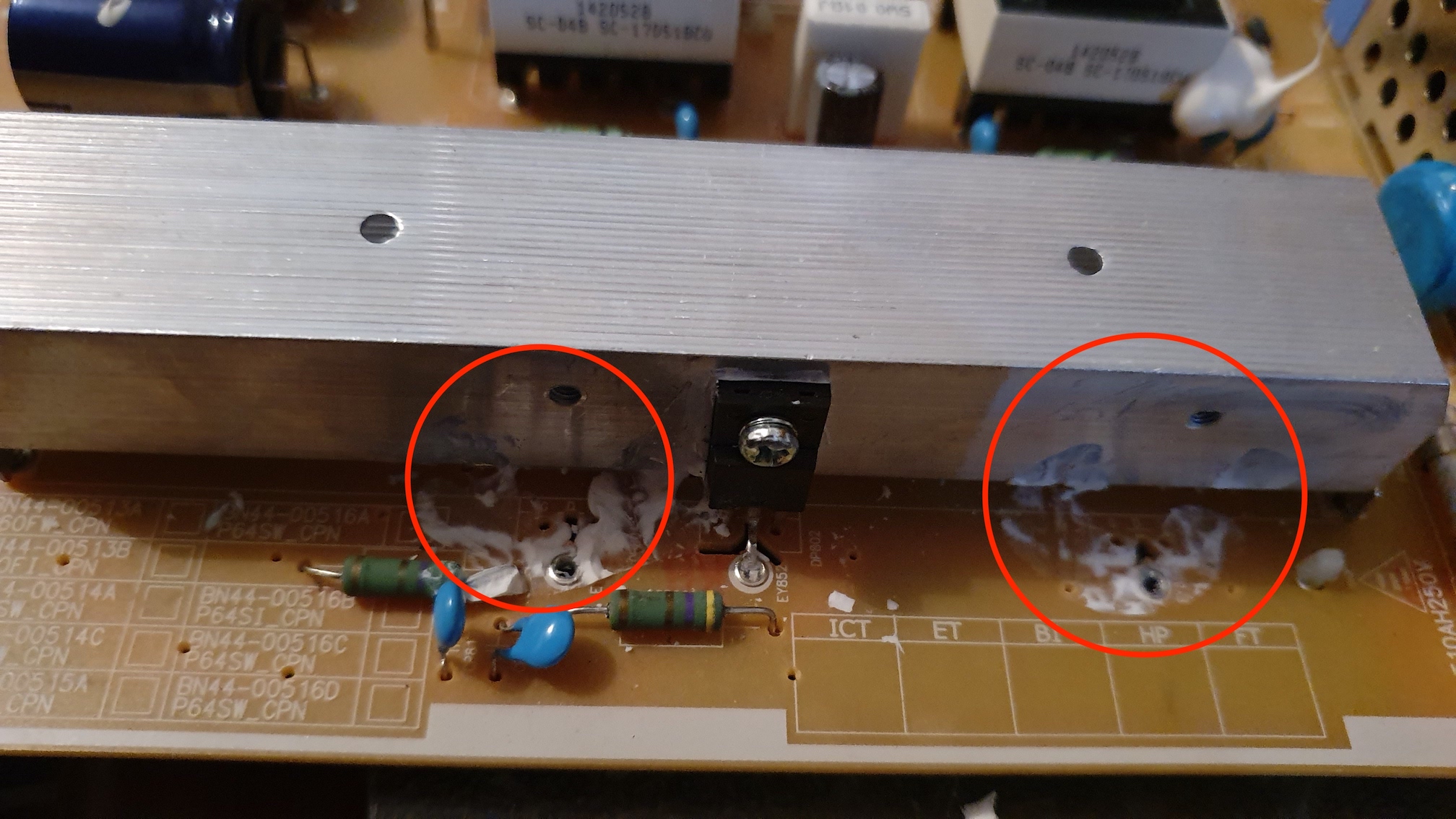
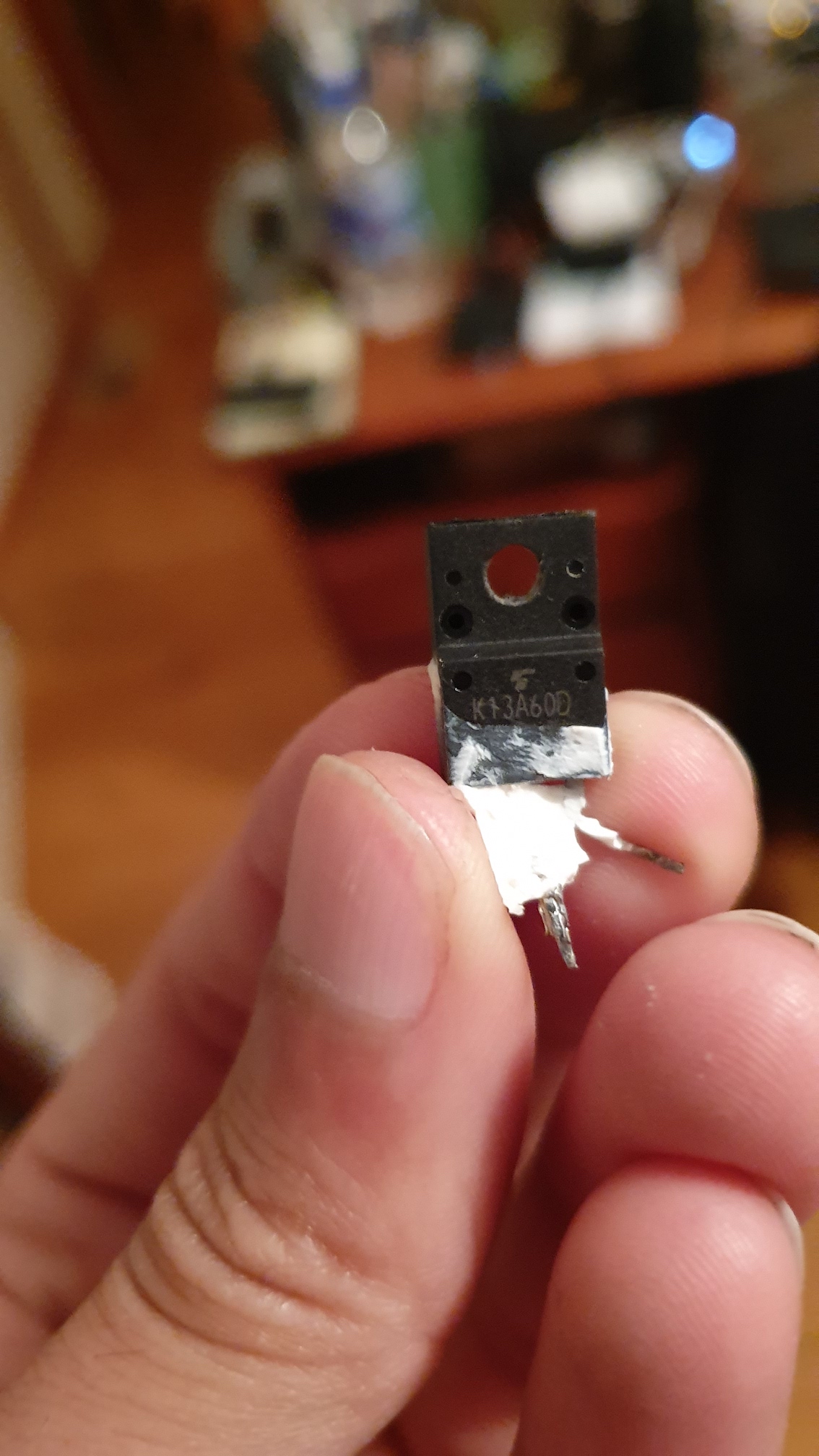
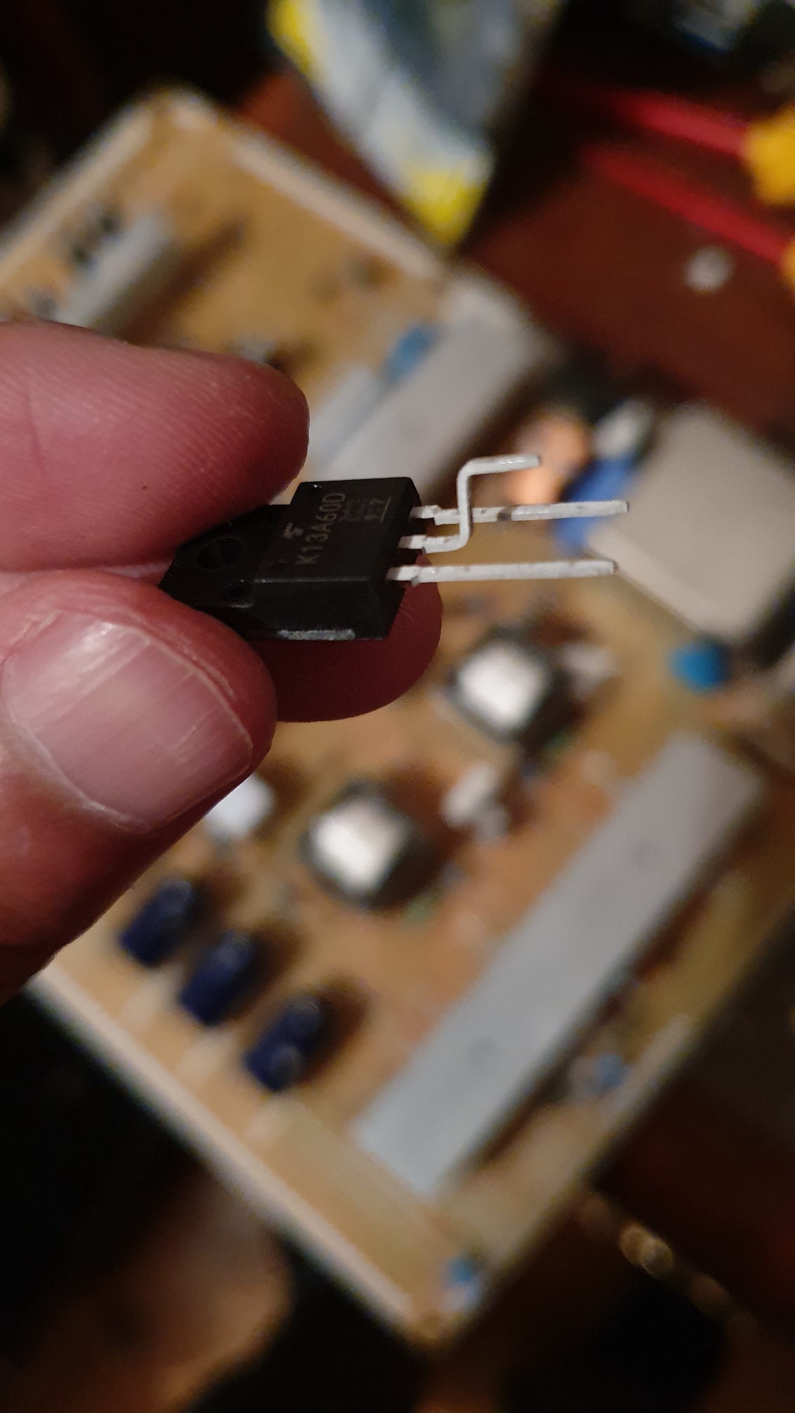
After taking the rectifier out of circuit, I continued to see if the diode failed because of a failure further downstream. The next set of components is the power factor correction circuit. There are two parallel circuits here which are mirrored exactly. Here I found one of the mosfets (TK13A60D) was shorted on all 3 terminals. A 3 way short is really bad as the gate driving circuitry was not exposed to 300VDC when it is only designed for 20VDC. The mosfets are covered in a silicon that can be removed easily if you use Isopropyl alcohol.
Each gate driver circuit consists of a push pull setup with an NPN and PNP transistor. Measuring each of these using diode test mode on a multimeter showed the transistors were ok. I then assumed based on the lack of burn marks and working transistors the gate driver has been spared thanks to the fuse and circuit breaker!
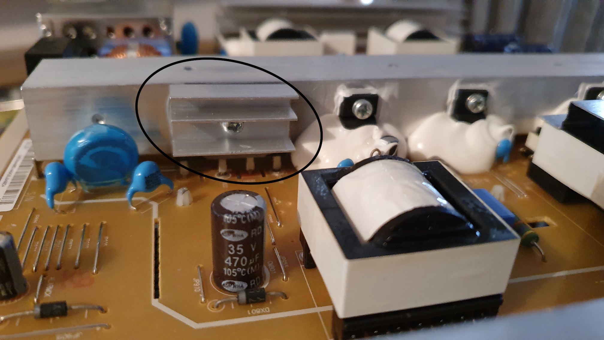
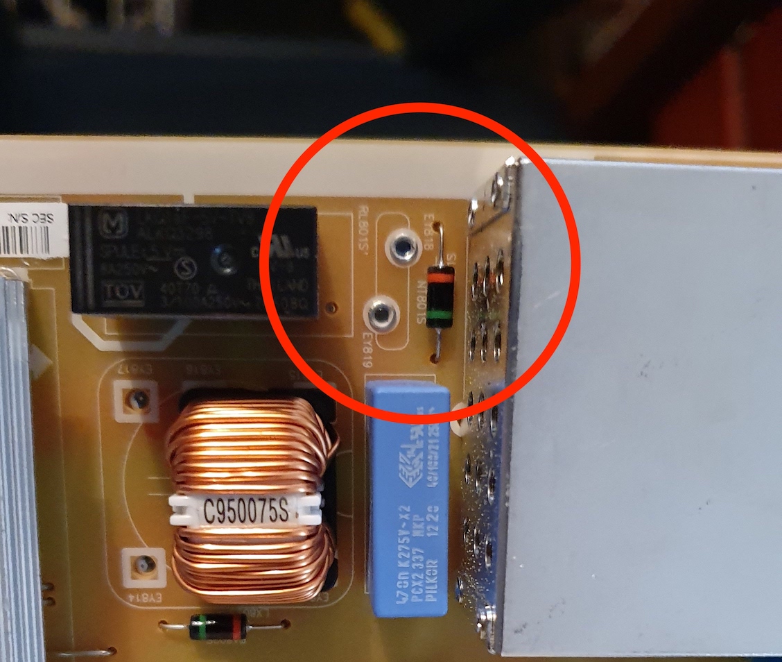
The last part that takes a beating in the event of a short is the inrush current limiter. It's designed to limit inrush current when the capacitors charge up in standby. It is wired in parallel to the PS ON relay. Visually this NTC had a hairline crack, however when I placed a finger on it, the device fell apart. Piecing it back together got me a part number of WTR15D080 which is an 8ohm 5A NTC [Datasheet].
Fix
I ordered the following parts:
| Product | Quantity | Supplier |
|---|---|---|
| TK13A60D Mosfet | 2 | Mouser |
| 10A 250V Slow Blow Fuse | 1 | Mouser |
| 35A 400V Bridge Rectifier | 1 | Rockby Electronics |
| 10Ohm 3A NTC | 1 | Rockby Electronics |
Desolder all the required components, and don't forget to apply thermal paste between the heatsinks and the components. Also you need to bend the mosfet legs in order for them to fit into the holes on the board. Use some silicon to reapply around the leads of the mosfets. This is to stop dust potentially shorting out the leads.
I also recommend going over the major solder joints (the riveted joints, like on the mosfet drains) with a soldering iron and new solder. These joints have a tendency to crack which will cause problems in the future.
Results
Replacing all those components above resulted in a decent TV being saved from landfill :)